Air Pilot Valve Guide: How It Works and Where It Fits
The actuator on a heating coil keeps moving, but the coil valve doesn't settle where the controls sequence expects. A technician checks the electrical command and the compressor, yet the actuator still responds slowly or inconsistently. In a mechanical room, the fault may be between those points: the air pilot valve needs enough control pressure at its pilot port to shift the main valve fully.
An air pilot valve uses a relatively small compressed-air signal to move a larger flow-control element. That lets a modest control signal direct air to an actuator without requiring the signal itself to carry the actuator's full flow. For building teams, understanding that relationship makes it easier to assess comfort complaints, actuator response, and equipment specifications.
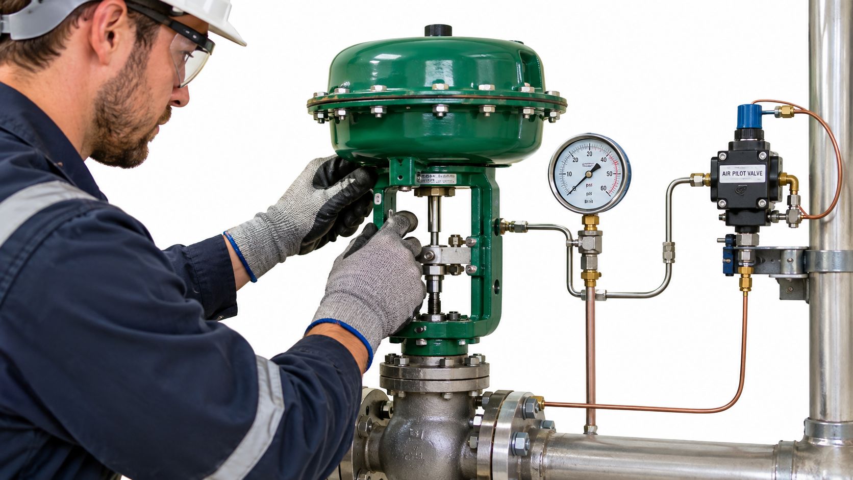
Table of Contents
- Why Small Pilot Signals Matter in Building Systems
- How an Air Pilot Valve Actually Operates
- Reading the Spec Sheet Before You Buy
- Common Applications in HVAC and Hydronic Systems
- Internal Pilot versus External Pilot Designs
- Commissioning Checks That Catch Problems Early
- Troubleshooting the Most Common Symptoms
- Connecting Air Pilot Valves to Building Metering Decisions
Why Small Pilot Signals Matter in Building Systems
A pilot signal is a control input, not the main flow that does the work. Compressed air reaches a piston or diaphragm in the valve's pilot stage. That movement shifts the main spool, which changes the connections between the valve's ports and directs air to, from, or through the downstream actuator.
The practical advantage is that a relatively small signal can control a larger flow path. In building systems, that arrangement can help operate actuators where a direct control device would need to handle more of the mechanical work. It also lets control logic sit at a convenient point while the valve and actuator are located near the equipment.
The same principle applies whether a technician is checking a heating coil actuator, a damper, or another pneumatic device. When an actuator hunts, moves slowly, or fails to reach its commanded position, the control command alone doesn't tell the whole story. The pilot pressure and the valve's ability to shift the spool matter too.
Field perspective: A signal at the controller doesn't prove that the actuator received enough pressure to move. Check what reaches the pilot port under operating conditions.
Pneumatic actuation remains useful in industrial and process settings where electrical actuation may be undesirable or where a pneumatic response suits the application. In building services, however, the selection still has to fit the actual equipment, operating conditions, and applicable requirements. A valve that looks appropriate by port size may still be unsuitable if its pilot-pressure needs, flow capacity, or pressure limits don't match the actuator and installation.
How an Air Pilot Valve Actually Operates
Start with the pilot stage. Compressed air enters a small control passage and acts on a piston or diaphragm. Think of it as a small push on a larger mechanism: the pilot doesn't need to move the whole actuator directly. Instead, it shifts the valve's spool, and the spool redirects the air that drives the actuator.
Inside a spool valve, the spool slides within the valve body. Its lands block selected passages, while the spaces between those lands allow air to pass between ports. When pilot pressure moves the spool, the connections change. A spring-return design uses a spring to push the spool back when the pilot signal is removed; other designs may use a second signal or another return arrangement.
The valve's port and position configuration tells you what it can do. A 2-way valve opens or blocks a path, making it suitable for simple start-and-stop flow control. A 3-way valve can supply an actuator in one position and connect it to exhaust in another, which suits devices that need air applied and then vented. A 4-way valve redirects air between actuator connections, allowing a double-acting actuator to move in opposite directions.
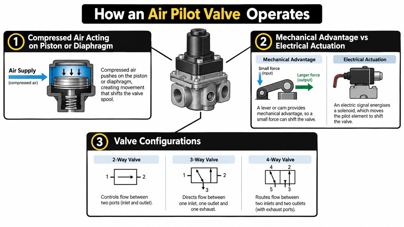
The key distinction is that the pilot signal controls the main flow path. It's a force multiplier in practical terms: the pressure acting on the pilot element shifts the spool, and the spool controls the air supplied to or exhausted from the actuator. For a related look at how a different type of building control component affects heat delivery, see this guide to how radiator valves work.
Canadian documentation illustrates why the principle has to be paired with product-specific compliance and pressure checks. A Ross Fluid Power registration document identifies Canadian Registration Number CRN 0C1409.53469087YTN and a maximum design proof pressure of 150 psig, equivalent to 10 bar. That is a limit for the documented product, not a universal rating for air pilot valves. Confirm the registration and pressure requirements that apply to the specific assembly and installation.
For a visual walkthrough of the operating idea, the video below shows an example of air pilot valve operation.
Reading the Spec Sheet Before You Buy
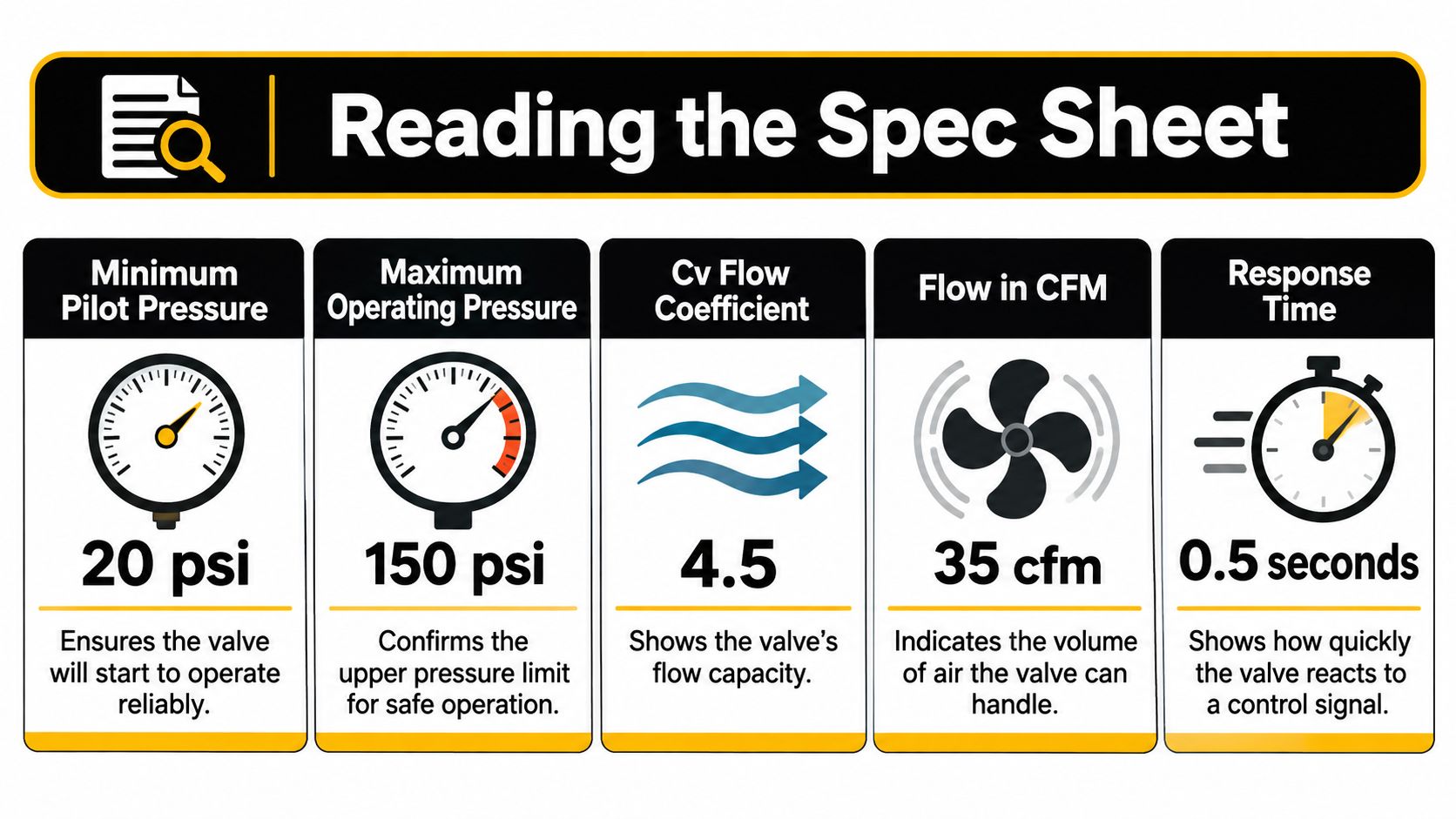
A retrofit can look fine on a schedule and still fail at the first cold start. Port size is the easy line to read, but it does not prove the valve can move the actuator under load. Start with minimum pilot pressure: the pressure the pilot stage needs to shift the spool. For a CSA-certified four-way valve sold in Canada, the listed minimum pilot pressure is 20 psi, with a maximum operating pressure of 150 psi, a Cv of 1.4, and a maximum flow of 161 cfm (Canadian product specifications).
Each value answers a different field question. Minimum pilot pressure is the “can it switch?” threshold: if pressure at the pilot port sags while the actuator is moving, the spool may stall between positions instead of completing a clean shift. Maximum operating pressure is a ceiling. Cv works like the size of a doorway for airflow, so a valve with too little capacity can leave the actuator filling or exhausting through a restriction and stretch the response the controls sequence sees.
Spec Line
What It Really Tells You
Minimum pilot pressure
Whether the valve can shift the spool with the pressure actually available at the pilot port.
Maximum operating pressure
The upper pressure boundary specified for the valve.
Cv
How much restriction the valve presents to airflow.
Maximum flow
The stated flow capacity under the product's specified conditions.
Response time
The valve's stated switching time, not automatically the installed actuator's full stroke time.
Temperature range
Whether the component is rated for the surrounding conditions.
The Parker B6 shows why the temperature line deserves the same attention as pressure. Its listed specifications include 2.7 Cv, 62.5 cfm maximum flow, 20 psi minimum operating pressure, 145 psi maximum pressure, 37 ms stated response time, and an operating range of 32–120 °F (Parker B6 specifications). That lower limit begins at freezing, so a valve outside a warm compressor room may need an enclosure, heat, or a component rated for the colder ambient.
Read response time as the valve's own bench figure, then ask what the building adds. Long tubing runs, tight fittings, clogged silencers, and actuator volume can make the installed stroke slower even when the catalogue switching number is short.
Common Applications in HVAC and Hydronic Systems
A comfort complaint lands on the coldest morning of the heating season, and the work order history shows the same unit flagged twice already. Somewhere between that complaint and the mechanical room, an air pilot valve either turned a control command into physical movement or failed to. The device works like an electrical relay: a small signal at the pilot port switches a much larger pneumatic supply, which is what moves the actuator.
In a heating or cooling coil circuit, the sequence calls for the actuator to change position as building load changes. The pilot valve directs the air that makes it happen. It does not measure room temperature or decide what position is needed. It carries out the switching the controller commands.
Damper actuators use the same arrangement. The damper changes the air path while the pilot valve meters air to the actuator. When damper response lags the sequence, check the control signal, the pilot pressure available at the valve port, and the flow path itself before condemning the damper. A valve Cv sized too small for the actuator's volume produces a slow stroke that reads like a controls failure on the front end.
A valve can shift cleanly on a bench and still lag in the field once tubing runs, fittings, exhaust routing, and actuator volume join the circuit.
Larger process loops follow the same logic where the installation calls for a pneumatic signal or where electrical equipment is undesirable. The configuration depends on what the actuator must do: open or close a flow path, vent a single-acting device, or reverse a double-acting actuator.
In multi-family and mixed-use properties, unit-level hydronic systems depend on the same reliable control chain to deliver the intended heating or cooling response. A sight flow indicator gives staff a visual reference when they need to confirm fluid is moving through a circuit, which separates a valve problem from a flow problem. For broader plant planning, teams can also create a boiler maintenance schedule that assigns recurring inspection and service tasks.
When a comfort complaint traces back to this equipment, keep the valve's role distinct from the rest of the chain. The controller issues a command, the pilot stage shifts the spool, and the actuator moves the connected equipment. A fault at any link produces a similar complaint, so a gauge reading at the actuator port during a commanded stroke tells a commissioning agent far more than swapping parts on symptoms alone.
Internal Pilot versus External Pilot Designs
An internally piloted valve works like a self-powered relay. It taps a small amount of its own supply air and uses that pressure to shift the main spool, so one connection feeds both the flow path and the control function. That simplicity carries a condition: the valve can only pilot itself as reliably as the supply feeding it. A typical internally piloted valve lists a minimum operating pressure and a stated response time in its catalogue data, and as noted earlier, those published figures describe the component rather than guaranteeing suitability in every installation. What decides the outcome is the pressure that reaches the pilot passage while the rest of the circuit is drawing on the same line.
An externally piloted design takes its shifting pressure from a second, separate air source. That supply can hold steady even when the main line is too low or too variable to move the spool on its own, or when the process air must stay isolated from the control circuit. The trade is an added supply path, with extra tubing, extra fittings, and one more line a technician has to trace during a fault call. The arrangement is often paired with actuated valve assemblies such as a ball valve with actuator, where a dedicated pilot line keeps the actuator responsive regardless of what the main line is doing.
The choice between them is a supply question, not a valve-quality question.
Decision point
Internal pilot
External pilot
Pilot-air source
Draws from the valve's own supply.
Fed by a separate pilot supply.
Best fit
The supply meets the minimum pilot requirement during operation.
The main supply cannot reliably provide pilot pressure, or must stay isolated from it.
Installation check
The supply holds the minimum pilot pressure while the circuit is under demand.
The separate source is connected, regulated, and maintained.
Common risk
A sagging supply leaves the spool short of full travel.
The extra pilot circuit adds a point of failure to inspect.
A cold mechanical room does not, by itself, settle the choice. Low temperatures can stiffen seals and thicken any moisture in the tubing on either arrangement, so the first check is whether the valve and its components are rated for the actual ambient conditions at the mounting location. Only after that rating is confirmed does the pilot question come into play: can the chosen supply move the spool on the coldest morning the plant will see? For a related look at how pilot pressure requirements are handled in a hydraulic context, this pilot check valve sizing guide is a useful reference.
Commissioning Checks That Catch Problems Early
Catalogue figures describe the component. Commissioning checks establish how it performs in its installed location. A useful routine focuses on pressure at the pilot port, the actuator's movement, the valve's fail position, and the conditions under which the equipment must work.
Begin with a pressure gauge at the pilot port. Observe it while the actuator is moving, because pressure may fall during demand even when the compressor or header reading looks acceptable. If pressure at the pilot point drops too low, inspect tubing length and size, fittings, and any restriction between the supply and the valve.
Next, record the actuator's stroke time and confirm that the valve reaches its intended position. Don't assume a catalogue response time represents the full installed stroke. The actuator, connected equipment, tubing, and exhaust route all affect what the operator sees.
Check
Where to Measure
Acceptance Cue
Pilot pressure
At the valve's pilot port while the actuator moves
Meets the selected valve's minimum pilot-pressure requirement during movement.
Supply pressure
At the valve inlet under operating conditions
Stays within the valve's specified operating limits.
Stroke time
At the actuator or driven equipment
Matches the sequence and equipment requirements.
Fail position
At the actuator or controlled device when the signal is removed
Reaches the documented safe or intended position.
Ambient temperature
At the valve's installed location
Remains within the component's rated range, or the installation provides suitable protection.
Repeat these checks at the coldest expected operating condition, especially if the valve is in an exposed or unheated area. Record the temperature alongside pressure, stroke time, and fail position so later troubleshooting has a useful baseline. Keep the acceptance criteria tied to the selected equipment and control sequence rather than inventing a single target for every installation.
Troubleshooting the Most Common Symptoms
A damper actuator that creeps instead of stroking is a pressure problem until the measurements prove otherwise. Treat the pilot signal like the hand on the valve spool: it has to push the spool far enough, hold it there during travel, and let it return when the signal is removed. If pressure looks good only at rest, the line may still sag while air is moving.
Start where the symptom shows up. Confirm the control output is calling for movement, then put a gauge on the pilot port and watch it through the full stroke. A reading that seems healthy before travel but dips as the actuator moves points to tubing that is too long or small, a kinked fitting, a clogged quick exhaust, or a shared supply that cannot feed simultaneous loads.
If pilot pressure stays steady, move from signal to capacity. The valve Cv sets how much air can reach the actuator and how quickly the opposite chamber can vent. A restricted exhaust or oversized silencer can make a correctly selected valve feel weak, because the spool has shifted but the actuator still has air trapped behind it.
Mechanical drag sits later on the list for a reason. Moisture, oil carryover, dust, or ice can raise spool friction so the pilot pressure wins only part of the travel. That produces a familiar pattern: motion starts, stalls, then jumps when pressure builds.
Use the same order for unstable cycling: command, pilot pressure under load, Cv and exhaust, then spool condition. For cold locations, compare the temperature at the installed valve with its rated range and look for condensate that can freeze in the body, muffler, or exhaust path, as noted earlier. A warm compressor room does not guarantee the same conditions at a rooftop, parking garage, or unheated penthouse.
Connecting Air Pilot Valves to Building Metering Decisions
A rooftop actuator that hesitates on a cold morning can look like an energy problem on a dashboard. The air pilot valve has no meter register and no billing role. Its job is operational: help the control system move the device that affects consumption. If the valve shifts late, vents slowly, or stalls partway, a heating or cooling sequence can run longer than intended, and property teams may read the resulting comfort complaint or utility trend as a metering issue.
Reliable controls and measured consumption answer different questions in multi-unit buildings. Controls govern how equipment responds; submetering assigns measured utility use to units or shared areas, where permitted and appropriate. Thermal energy submetering, for example, gives property teams a way to track heating and cooling use at the unit level. That data becomes easier to trust when the field devices upstream of it have been selected, installed, and checked with the same care.
Before a retrofit or commissioning visit, tie the pneumatic details to the building's operating goals:
- Actuator requirements: Confirm minimum pilot pressure and intended fail position at the actuator connection so the reading reflects the device that moves.
- Valve selection: Match configuration, flow capacity, pressure limits, and temperature rating to the installed location.
- Field verification: Note pilot pressure during travel, stroke behavior, and ambient conditions, especially in unheated spaces.
- Metering scope: Decide which utilities and areas need unit-level or common-area measurement, and confirm jurisdictional requirements.
These checks separate a control problem from a metering question. When both are addressed clearly, property teams can compare comfort complaints and consumption patterns with better context, rather than assuming one system explains the other.
Axis Meter Solutions provides turnkey utility submetering for multi-family, condominium, mixed-use, and commercial properties, including equipment, installation, commissioning, tenant billing, and ongoing service. If you're planning a metering programme alongside controls or retrofit work, visit Axis Meter Solutions to discuss the building's requirements and implementation options.
Ready to Optimize Your Utility Management?
Tell us about the property, utility, number of units, and your billing or monitoring goals. We'll help you identify the right next step.
Book a Call