Water Valve 3 Way Guide for Property Managers
A maintenance call comes in from a suite with no hot water. The technician finds a valve on a shared riser, changes its position, and restores service to that branch. But the same change also affects flow to other suites, and no one is certain whether the valve has isolated the right line or created an unintended connection between water sources.
That's why a water valve 3 way deserves more thought than its compact body suggests. In a multifamily or commercial building, it can help route water or control heating, but it doesn't automatically provide backflow protection or safe isolation. The right choice depends on what the valve must do, what systems it connects, and what local requirements apply.
Table of Contents
- Why Three-Way Valves Matter in Multifamily Buildings
- How a Three-Way Water Valve Actually Works
- Mixing Valves and Diverting Valves Compared
- Port Configurations and Actuator Options
- Where Three-Way Valves Are Used in HVAC and Plumbing
- How to Choose the Right Valve and Metering Partner
- Installation, Flow Direction, and Safety Checks
- Your Next Step Toward Safer Water Systems
Why Three-Way Valves Matter in Multifamily Buildings
A three-way valve can look like a small detail on a mechanical-room drawing. For a property manager, though, its position may affect temperature control, maintenance access, and the routes water can take through a building. On a shared riser, a change made to serve one suite can have consequences for other suites downstream.
Consider a technician servicing a heating coil. The valve is meant to redirect water through a bypass while the coil is isolated. If the valve is installed or operated in the wrong configuration, the coil may not receive the intended flow, or another branch may be affected. The problem might show up as an uncomfortable suite, a call-back for the contractor, or a system that behaves differently from what the building controls indicate.
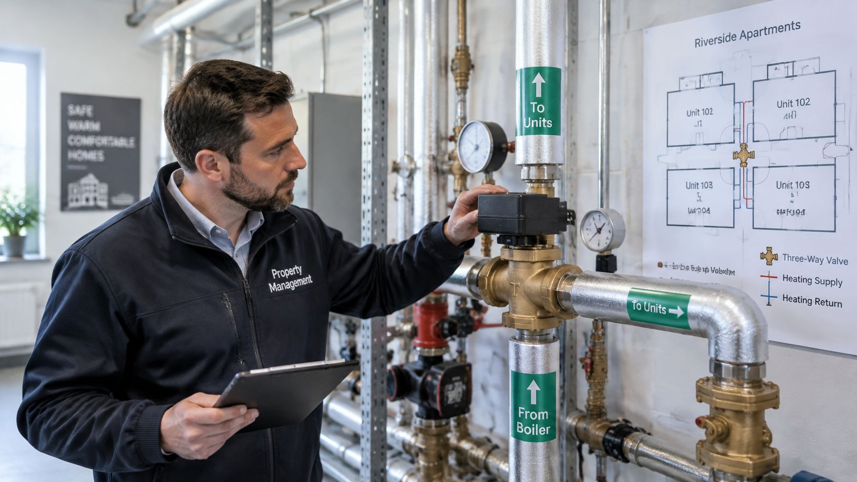
The key distinction is that a three-way valve is a flow-routing component, not automatically a safety device. It may direct flow between branches, but it shouldn't be assumed to protect drinking water from backflow or to replace a dedicated isolation valve. In California, cross-connection rules require the level of protection to match the hazard, which may call for an approved backflow-prevention assembly or an air gap rather than a different valve position (California's Cross-Connection Control Policy Handbook).
For a property manager, the useful question isn't, “Do we have a three-way valve?” Ask what it connects, what its normal position should be, and whether another device is required to protect the potable supply. Those questions help separate a convenient control fitting from a building safety requirement.
How a Three-Way Water Valve Actually Works
Think of a three-way valve as a railway switch. The switch doesn't create the train or its destination. It changes which track is connected. A valve does something similar with water, either directing a stream to a selected path or combining streams into a shared outlet.
The three openings are called ports. One is often designated the common port, the connection shared by the valve's available flow paths. The other two may be identified as Port A and Port B. Depending on the valve's design and how the pipes are connected, the common port can be the inlet or the outlet.
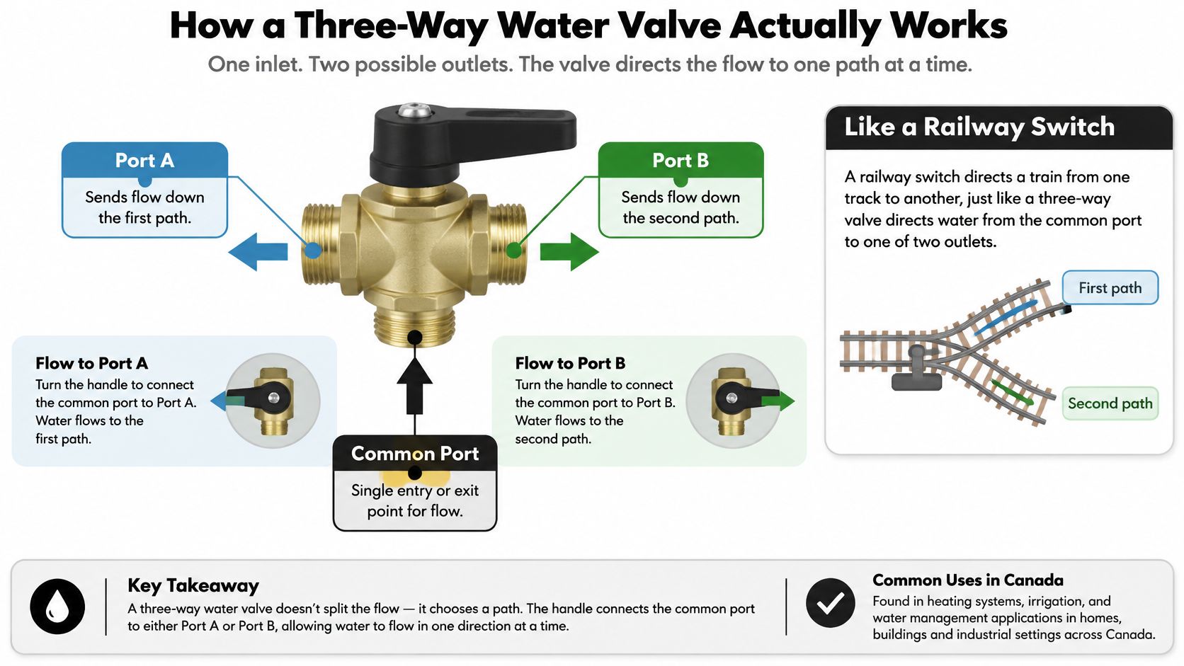
For example, in a diverting arrangement, water enters through the common port and the valve sends it toward Port A or Port B. In a mixing arrangement, water enters through the other two ports and leaves through the common port. Some valves can connect more than two ports in certain positions, so don't assume every three-way valve has the same flow pattern.
A three-way valve routes flow. It doesn't generate pressure, guarantee a shutoff, or make an unsafe water connection safe.
Inside the valve, a plug, ball, or other internal part moves as the handle or actuator turns. That movement opens one pathway and restricts another, according to the manufacturer's port diagram. The labels load port and bypass port are useful in hydronic heating: the load port directs water through the coil or other equipment, while the bypass port provides an alternate route.
When you're looking at a valve in the field, follow the pipework and check the manufacturer's diagram before relying on the handle position. The external shape alone doesn't tell you which ports are connected inside.
For a visual overview, the following video introduces three-way valve operation.
Mixing Valves and Diverting Valves Compared
The practical difference is the job each valve performs. A mixing valve takes flow from two inlet paths and combines it into one outlet. A diverting valve takes flow from one inlet and directs it toward one of two outlet paths. Port count alone won't tell you which one you have; check the piping arrangement and the valve's flow diagram.
Valve Type
Port Function
Typical Application
Flow Behavior
Mixing
Two inlets feed one common outlet
Blending water or controlling flow through hydronic equipment
Combines streams at the outlet
Diverting
One common inlet feeds either of two outlets
Routing water toward a selected branch or bypass
Sends flow along the selected path
A tempering or control application may need two incoming streams blended to achieve a desired supply condition. A bypass arrangement may instead send a single stream around equipment or toward another branch. These jobs can both use three-way valves, but they don't call for the same port connections or internal flow pattern.
A common source of confusion is that a valve body may have three ports even when the system uses it for only one specific purpose. Don't infer the duty from the number of pipes or the actuator alone. Ask the contractor to show which port is common, which path is open in each position, and whether any position connects multiple ports.
If the wrong type is installed, the result can resemble a controls problem. A coil may fail to respond as expected, a bypass may carry unintended flow, or a control signal may move the valve without producing the required routing. Before changing the controller or actuator, confirm that the valve's flow pattern matches the system design.
Port Configurations and Actuator Options
Before a valve is installed, trace the port labels against the piping diagram. The manufacturer identifies the common port and specifies which connections serve as inlets or outlets. Reversing those connections can send water along an unintended route, even if the valve and controls appear to operate normally. In a multifamily or commercial building, confirm the intended flow path also preserves required isolation and does not create an unapproved cross-connection or backflow risk.
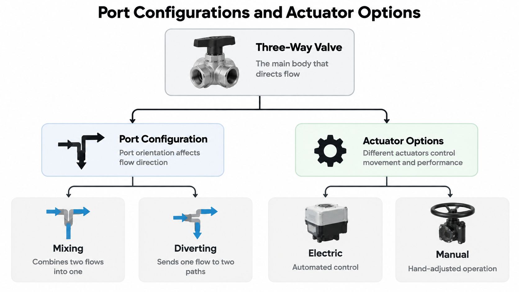
The actuator moves the valve. A manual actuator uses a handle or lever, while an electric actuator responds to an electrical control signal. Some systems use pneumatic actuation. Whichever type is fitted, check that its travel and operation suit the valve's duty. A control signal may be correct while the valve routes water incorrectly because its port arrangement or actuator setup does not match the design.
Some valves switch between two positions, directing flow along one path or another. Others modulate across a range, adjusting flow gradually. The difference matters when a heating or cooling controller requires gradual adjustment rather than a simple changeover.
For a Canadian-market V5013 series, the manufacturer's limits vary by service. Its specification permits water and glycol mixtures up to 50% concentration, with maximum differential pressure of 345 kPa (50 psi) in two-position service, 172 kPa (25 psi) in modulating service, and 138 kPa (20 psi) for quiet-water service (V5013 series specification). These ratings show why connection size alone cannot establish suitability. Check the actual pressure conditions and fluid compatibility against the documentation for the specific model.
For an automated valve, compare actuator and control requirements with the building's controls and access needs. A ball valve with an actuator provides another example of powered valve operation, though the right choice still depends on the system design and applicable safety requirements.
Where Three-Way Valves Are Used in HVAC and Plumbing
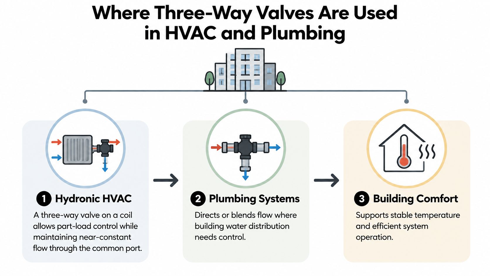
A heating coil in a multifamily building needs enough water to meet changing demand, while the rest of the hydronic loop still needs predictable circulation. A three-way control valve can direct some water through the coil and some through a bypass, much like a junction that splits flow between two routes. Whether that arrangement works depends on valve sizing and actual piping pressures, not pipe diameter alone.
Valve authority affects how steadily the valve controls temperature. If the valve has too little authority, a small movement near the start of its travel can cause a large change in flow, making control less stable. For hydronic applications, designers assess authority alongside the pressure drops across the branch and riser, then select a valve characteristic suited to the load and bypass paths. The right setup depends on the system design, so port diagrams alone do not establish suitability.
An oversized valve may have too little pressure drop to control temperature well, leading to poor regulation or frequent actuator movement. An undersized valve can increase pumping demand, cause noise, or restrict design flow. The designer should account for expected flow and differential pressure, then check the choice against actual branch and riser conditions.
In plumbing, three-way valves may route, bypass, or mix water. Their ability to redirect flow does not, by itself, protect potable water from contamination. For example, a connection between potable water and graywater is a cross-connection concern under California guidance. Potable-water makeup requires an air gap or approved backflow-prevention device, and a graywater diversion valve must be accessible and clearly labelled (San Diego County graywater guidance). In practice, code and backflow requirements govern the design, even when a valve arrangement seems convenient.
A flow meter can help property managers see how water moves through a building, but it does not replace sound valve design or backflow protection. For a plumbing project, this guide to an in-line water flow meter explains where measurement equipment can fit into a system.
How to Choose the Right Valve and Metering Partner
Start with the system's job, not the product catalogue. Ask whether the valve must mix two streams, divert one stream, or provide a bypass arrangement. Then have the designer establish the required design flow and differential pressure, calculate the required Cv, and verify the valve's authority against the actual branch and riser pressure drops.
Next, confirm fluid chemistry, temperature, materials, port arrangement, and actuator duty. A hydronic valve carrying a glycol mixture needs to be selected for that fluid, not treated as though it were handling water alone. In Ontario, plumbing supply fittings are subject to the applicable code requirements, including references to ASME A112.18.1/CSA B125.1 for plumbing supply fittings (Ontario Building Code, plumbing provisions).
Oversizing lowers the valve's pressure drop and can reduce authority, which may impair zone-temperature control. Undersizing can increase pump energy and contribute to noise or insufficient flow. Ask the engineer or contractor to explain the sizing basis and provide the manufacturer's flow diagram, rather than approving a valve solely because its connections fit the existing pipe.
Metering is a separate decision, but it often belongs in the same building conversation. Axis Meter Solutions provides full-service utility submetering for multifamily, condominium, mixed-use, and commercial properties in Canada and the United States. Its services include water submetering for suites and common areas, with leak and flood detection included in every installation, alongside metering, installation, commissioning, billing, and ongoing service. The company describes a $0 upfront cost structure, provider-owned equipment over a standard 20-year term, and a typical 8–10 week timeline from agreement to live meters.
A valve contractor or building engineer is the right partner for defining flow paths, selecting components, and confirming code requirements. A turnkey metering provider may be relevant when the project also needs water-use allocation, leak detection, tenant billing, or long-term meter support. Keep those scopes clear: metering helps measure use; it doesn't approve a valve arrangement or replace a required backflow assembly.
Installation, Flow Direction, and Safety Checks
Before installation, compare the valve body markings with the approved piping diagram. Confirm the common port, the direction of flow, and the path associated with each actuator position. If the valve has a flow arrow or a manufacturer's connection diagram, don't ignore it just because the pipes can be connected another way.
Then check how operators will use the valve. Keep it accessible, and label its normal, bypass, service, and emergency positions clearly. A position that seems convenient for maintenance can create a hazard if it isolates equipment that must remain protected or leaves staff unsure how to restore the system safely.
California's water-heater requirements illustrate why a three-way valve isn't a universal replacement for dedicated isolation and safety controls. Newly installed instantaneous water heaters must have isolation valves on both the incoming cold-water and outgoing hot-water piping. However, a shutoff must not be placed between the water heater and its temperature-and-pressure relief valve, or in the relief discharge path (California Energy Commission water-heater guidance).
Where a backflow preventer is required in California, it must be tested after installation, relocation, or repair before it's placed into service, and routine testing must occur at least annually. The required protection depends on the identified hazard, so a three-way valve shouldn't be treated as a substitute for the specified approved device. When planning work, a resource on plumbing inspection costs and findings can help owners understand what an inspection may identify, while the building's engineer or authority having jurisdiction should confirm the required corrections.
For the piping design, check that the specified valve connections and pipe dimensions match the system. This guide to copper pipe diameters can provide helpful background, but it isn't a substitute for the project drawings or applicable code.
Use a commissioning check that records the result, not just the fact that someone turned the handle:
- Normal position: Confirm the expected path is open and the system serves its intended loads.
- Bypass position: Verify that flow follows the designed route without creating an unintended connection.
- Service position: Confirm the equipment being worked on can be isolated without defeating a safety control.
- Emergency position: Label the safe action clearly and make sure building staff know when to use it.
Your Next Step Toward Safer Water Systems
Most three-way valve decisions become clearer when you answer three questions. Is the application mixing or diverting? Could the connected branches create a cross-connection? Can staff reach, identify, and operate the valve without isolating a required safety device?
Those answers put the fitting in context. A valve is one part of a water system that may also require hazard assessment, approved backflow assemblies, commissioning, and ongoing inspection records. Treating the valve as a standalone solution is risky, especially when potable water, graywater, irrigation, or shared building equipment is involved.
A practical first move is to review the building's valve inventory alongside its cross-connection-control plan. For each valve, note its purpose, port arrangement, normal position, connected water sources, required protection, and any maintenance or test records. If the documentation doesn't establish what the valve controls, ask a qualified plumbing or mechanical professional to verify the installation before changing its operating position.
If your building is also considering suite-level water measurement or leak detection, define that work separately from valve selection. Clear metering can support accurate cost allocation and help staff identify unusual water use, but it won't correct an unsafe flow path. The project should coordinate the measurement plan with the plumbing layout, access requirements, and the people responsible for maintenance.
Start by choosing one mechanical room, riser, or shared hot-water system and checking its valve labels against the drawings. Record anything uncertain, then have the appropriate engineer or contractor confirm the intended routing and safety requirements before the next service call.
Axis Meter Solutions provides turnkey utility submetering, including water meters for suites and common areas with leak and flood detection. If you're reviewing water routing alongside metering or leak monitoring, visit Axis Meter Solutions to discuss a scope that fits your building.
Ready to Optimize Your Utility Management?
Tell us about the property, utility, number of units, and your billing or monitoring goals. We'll help you identify the right next step.
Book a Call